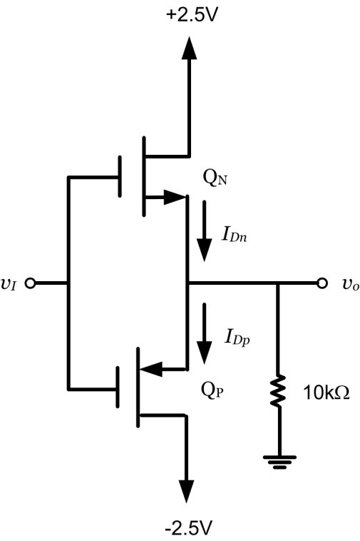
The body effect alters the threshold voltage VT and can be utilized to adjust the transistor’s properties dynamically. The transistor will suffer from the body effect if the voltage between the body and the Source is not zero. The fourth port, known as the body, is attached to the transistor’s substrate. The Body-EffectĪlthough the Gate, Drain, and Source characterize the transistor’s operation, the MOSFET is essentially a four-pin device. NMOS and PMOS should, of course, be designed to work in a symmetrical manner. This ensures that the output pin is constantly connected to a predictable and stable voltage, which is crucial in digital systems. When the voltage VG is low, the NMOS is off and the PMOS is on, resulting in a low impedance path from the output to VCC when VG is high, the NMOS is on and the PMOS is off, resulting in a low impedance path to ground. One of the most common MOS structures, in particular, uses both: the CMOS (complementary MOS). NMOS and PMOS are also commonly employed in analog and digital microelectronics. The NMOS is more commonly employed due to its advantages however, many applications require the PMOS’s polarization characteristics.

Cut-off, triode, and saturation are the three modes of operation in an NMOS. NMOS logic is used to describe logic gates and other digital devices that use NMOSs. This permits an n-type channel to be formed between the Source and the drain, with electrons carrying a current from the Source to the drain via an induced n-type channel.

The holes in the body (p-type substrate) are forced away from the Gate when a voltage is applied. The n-type Source and drain, as well as a p-type substrate, make up an NMOS transistor. NMOS (NMOSFET) is a MOSFET type, as previously described.
#PMOS VS NMOS TRANSISTOR FULL#
With this new arrangement you will be driving the PMOS with the full 3.3V available, and you will probably see a perfect match in the currents if the mosfets are identical.ĭisclaimer: P transistors usually conduct less than their N counterparts because holes have a reduced (about 1/3) mobility wrt electrons.
#PMOS VS NMOS TRANSISTOR SERIES#
To fix this, try to swap the series for the PMOS driver. Since you have a diode up there you are probably missing at least 0.5V, which can explain the difference in currents that you see. The PMOS instead has its load on the source, so when you pull its gate to ground the source to gate voltage is not 3.3V, but it is something less. In the case of the NMOS you are driving the transistor with 3.3V to turn it on, since the source is always grounded. The drain current of a MOS transistor is a function of its gate to source voltage, while drain voltage has little effect to it. If all the components are identical, or 'symmetrical', this is because for the PMOS the load is connected on the source.


 0 kommentar(er)
